10+ dfd diagram in uml
It offers support for BPMN UML ERD DFD SysML. Data Flow Diagram Levels.

Looking To Download Root Cause Analysis Template Then You Are At The Right Place These Templates Help You Analyze Analysis Report Template Problem Statement
To create new DFD select Diagram New from the toolbar.

. The Use Case Diagram is a UML Diagram where the each use-case specifies the behaviour expected from software from the perspective of end-user and relation as well as provides brief overview for different components concerning interaction between use-case actors and systems. This UML diagram maker provides the best functionality expected from a UML tool like a large selection of supported diagrams. 在线Visual Paradigm - UML编辑器使用在线UML编辑器轻松绘制UML图其中包含功能强大的UML编辑工具即时UML语法检查和整洁的用户界面Visual Paradigm在线UML 图如类用例序列活动部署组件状态机和包图一键即时打开使用什么是UML中的类图类图通过显示该系统中的类和类之间的关系来.
Windows 7 8 10 versions supported. 25_____diagram in UML shows a complete of a modeled system at a specific time. Enter Context as diagram name and click OK to confirm.
Yes No Yes No Unknown Unknown Available from the Eclipse M2M project Model to Model. Provides API and Plugins RTF HTML Export. UML was initially developed by software developers but has been successfully used in business process modelling with a more object-oriented approach to its 14 UML diagram types.
Learn from diagram examples and start creating your diagrams online. Later around 196070s Charles Bachman developed a type of Data Structure Diagram which further contributed to the development of the Unified Modelling Language UML widely used in software design. They find usage in some of these below key areas.
In 1-level DFD the context diagram is decomposed into multiple bubblesprocesses. A context diagram is a data flow diagram that only shows the top level otherwise known as Level 0. The Use-Case Diagram is used to prepare present and understand functional.
The main objective is to represents the flow of control in program. Draw data flow diagrams can be made in several nested layers. Download Use Case Diagram.
ERD Archimate flowcharts DFD wire frames user stories and much more. This is very beneficial for both analysis and communication. A Sequence B Collaboration C Clas D Object Answer.
Name the new process System. Biasanya DFD banyak digunakan oleh seseorang yang bekerja di bidang sistem informasi. We cover any subject you have.
Essay Help for Your Convenience. 2-level DFD goes one step deeper into parts of 1-level DFD. It can be used for creating infographics which is used for data visualization.
Diagram ini dipopulerkan oleh Ed Yourdon dan Larry Constantine pada akhir 1970-an dalam bukunya yang bertajuk Structured Design. DFDs can also be used for the visualization of data processing structured designOn a DFD data items flow from an external data source or an internal data store to an internal data store or. Diagrams under modeling categories such as UML BPMN etc.
Learn about UML BPMN ArchiMate Flowchart Mind Map ERD DFD SWOT PEST Value Chain and more. Why Use ER Diagrams. At this level there is only one visible process node that represents the functions of a complete system in regards to how it interacts with external entities.
The main objective is to represent the processes and data flow between them. Diagram under Casual drawing category provides 150 types of diagrams charts and business. BOUML is a UML diagram designer which is programmed in Qt and C.
Collage Maker Showcase those special moments and put them all together into one unique design. Can transform UML EMF models into other models. In the New Diagram window select Data Flow Diagram and click Next.
I want a relationship between er diagram and uml diagram. A context diagram is a top level also known as Level 0 data flow diagram. How to Draw Context Level DFD.
In order to help you with that Visual Paradigm enables you to reverse your Java source code into UML sequence diagram so that you can gain a better understanding of Java source code by reading diagram instead of looking to a possibly thousand lines of source code. A data-flow diagram is a way of representing a flow of data through a process or a system usually an information systemThe DFD also provides information about the outputs and inputs of each entity and the process itself. Code engineering syntax consistency check etc.
Posted By freeproject on Monday September 5 2022 - 1412. DFD ERD diagrams etc are drawn for a system in the Final year project. Flow Chart Data Flow Diagram DFD 1.
Data flow diagram DFD adalah ilustrasi alur sebuah sistem. It is often used as the basis for data flow diagrams or DFDs as they are commonly known. Hingga saat ini DFD banyak digunakan dalam pengembangan.
Visual Paradigm provides both more formal notation modeling and casual drawing capability. 1091 The best writer. Photo Book Maker Capture your most cherished memories with our professional online photo book maker.
Free UML tutorials database tutorials for uml modeling use case modeling requirements capturing ERD DFD BPMN round-trip engineering and more. A data-flow diagram has no control flow there are no decision rules and no loops. Receive your papers on time.
Suggested Reading Data Modeling Tutorial. Specific operations based on the data can be represented by a. Mind Mapping ER Diagram DFD Flowchart CRUD Traceability Map Requirement Diagram and Requirement table.
Any Deadline - Any Subject. August 10 2022. It only contains one process node Process 0 that generalizes the function of the entire system in relationship to external entities.
Some of the benefits of a Context Diagram are. In this level we highlight the main functions of the system and breakdown the high-level process of 0-level DFD into subprocesses. From the Diagram Toolbar drag Process onto the diagram.
Comes with a data model for further manipulation ie. 1 Business Information. Synopsis ER-Diagram DFD and documentation of the project.
Get all these features for 6577 FREE. For example an inventory software used in a retail shop will have a database that monitors elements such as purchases item item type item source and item price. Well now draw the first process.
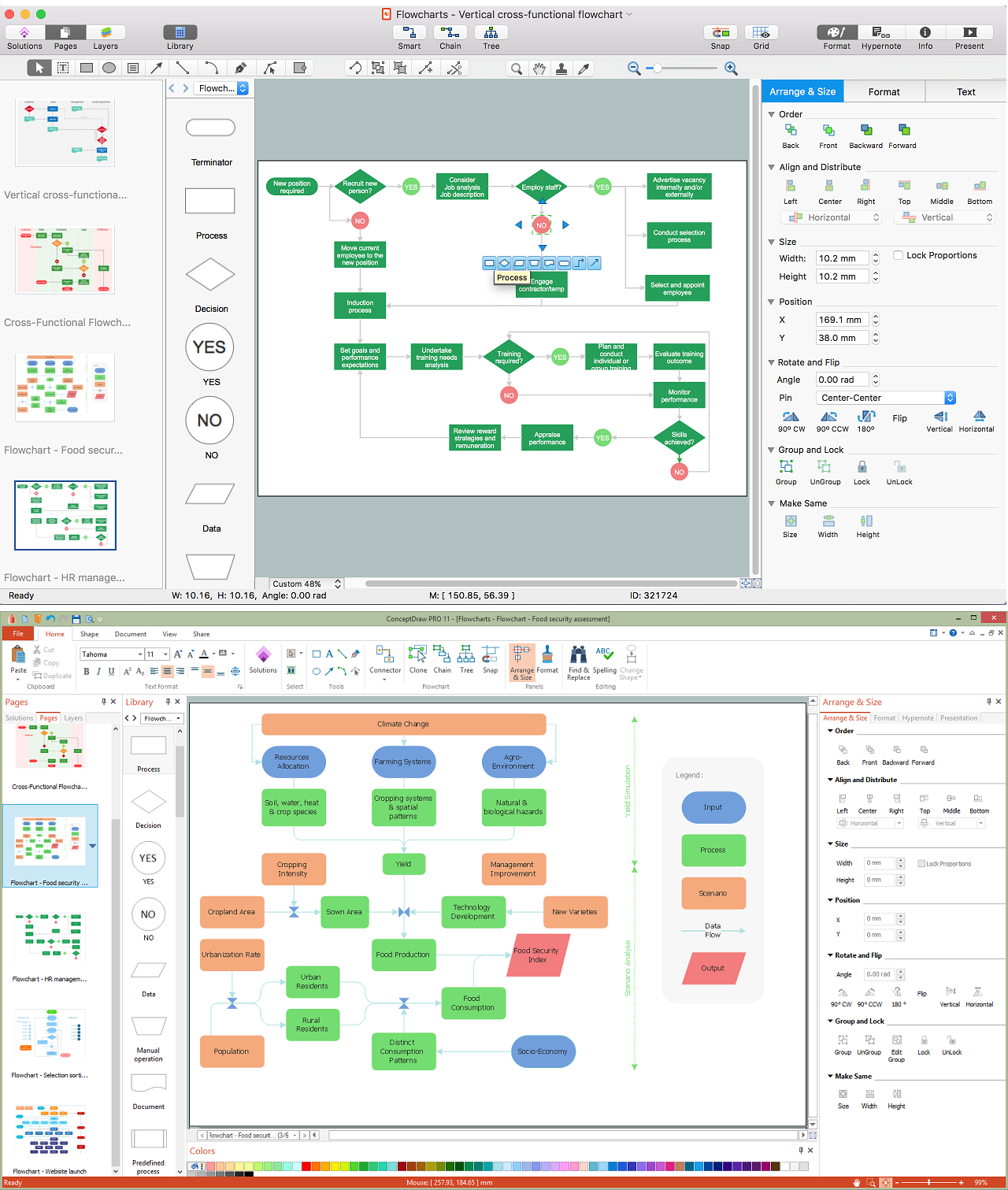
Diagram Creator Create flowchart UML ERD DFD ArchiMate BPMN floor plan wireframe PID and more. Set the deadline and keep calm. It permits you to specify and generate code in C Java Idl Php Python and MySQL.
Common Mistakes of Use Case DiagramsGraphically Represented inheritance in use case diagram. Unified modelling language UML is a more modern approach to modelling and documenting processes. Railway Reservation 22 45 Data Flow Diagram A data flow diagram DFD is a graphical representation of the flow of data through an information system.
It offers a complete tool like for process analysis system design database design etc.

Data Flow Diagram Wikiwand

Talk Data Flow Diagram Wikiwand
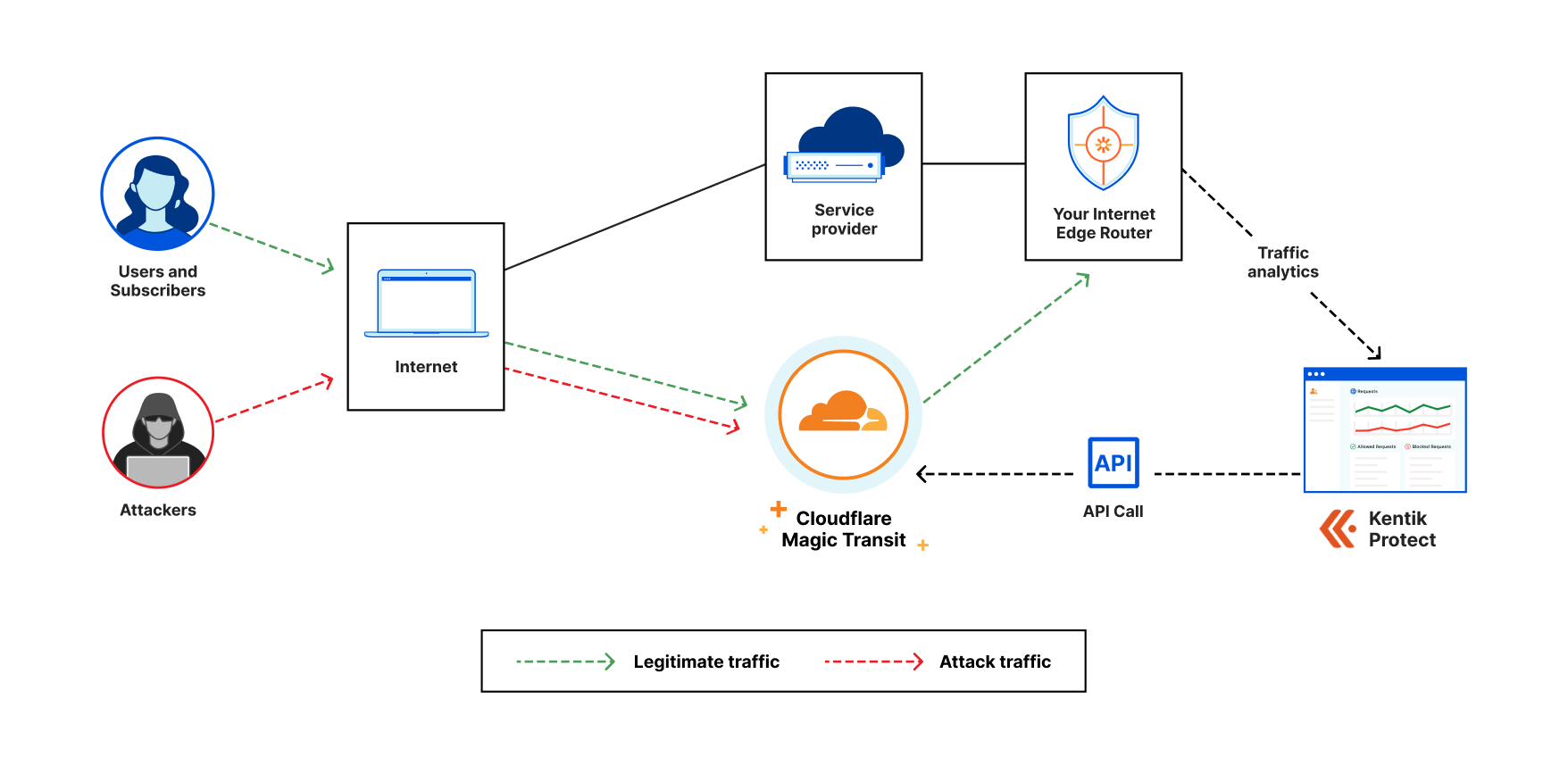
Magic Transit Noise

Structured Analysis Wikiwand

Structured Analysis Wikiwand
Event Partitioning Wikiwand
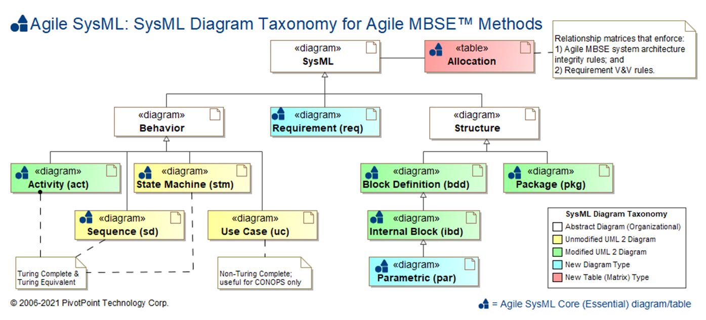
Sysml Faq What Is Sysml Who Created Sysml
Data Flow Diagrams Dfd Example Of Dfd For Online Store Data Flow Diagram Dfd Example Design Data Flow Dfd Library Data Flow Diagram For Restaurant Management System
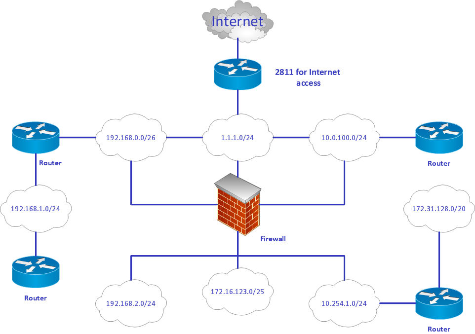
What Comes First Uml Diagrams Or Er Diagrams Quora
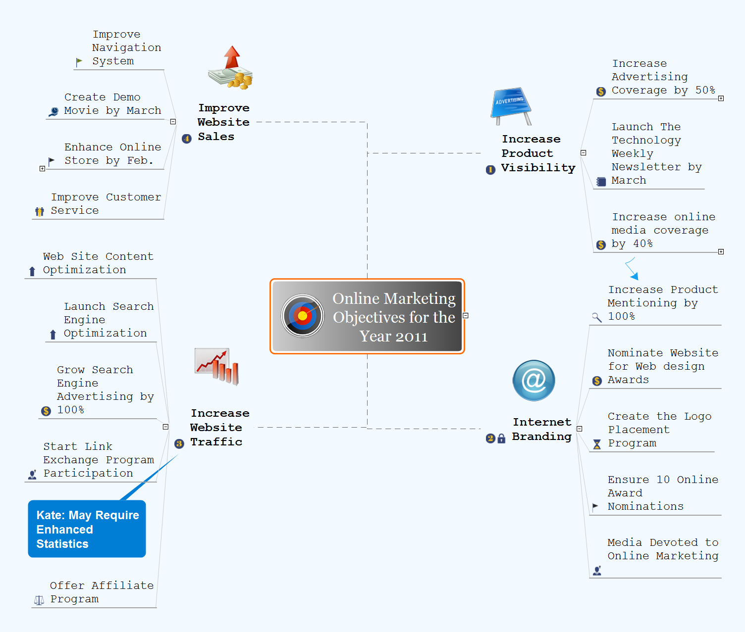
Gantt Chart Examples Gantt Chart Examples Online Marketing Objectives Marketing Launch Schedule Sample

In Which Order Should Uml Diagrams Be Placed In A Report Quora
Online Flowchart Maker Edrawmax Online

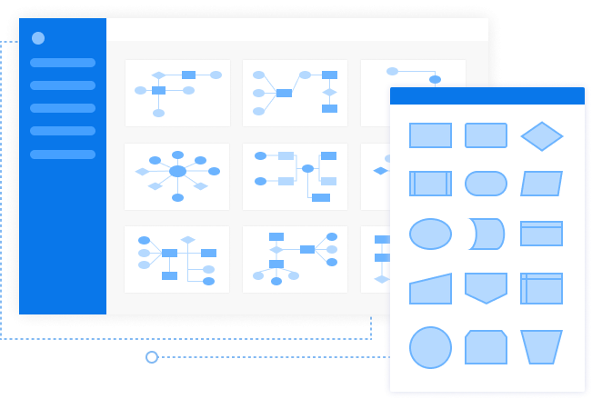
Basic Flowchart Symbols And Meaning Types Of Flowcharts Flowchart Components Difference Between Workflow And Flowchart
How To Make Good Usecase Diagram Dfd Uml For Software Engineering Quora
Database Flowchart Symbols Flow Chart Symbols Basic Flowchart Symbols And Meaning Database Flowchart Symbols

13 System Analysis Ideas Use Case Class Diagram Flow Chart

Pin On Flowchart Templates Examples